Follow along with the video below to see how to install our site as a web app on your home screen.
Note: This feature may not be available in some browsers.
- Welcome to RCCrawler Forums. It looks like you're enjoying RCCrawler's Forums but haven't created an account yet. Why not take a minute to register for your own free account now? As a member you get free access to all of our forums and posts plus the ability to post your own messages, communicate directly with other members, and much more. Register now ! Already a member? Login at the top of this page to stop seeing this message.
- Scale Rigs Brand Specific Tech
- Axial Brand Scale Rock Crawlers
- Axial SCX-10

Suspension: "Droop" (The What, Why, and How)
- Thread starter DowntownScience
- Start date Jun 11, 2015

DowntownScience
Rock crawler.
- Jun 11, 2015
I'm fairly new to the crawler scene (SCX10 for 2 years) and I don't own a 1:1. Droop is something that I'd heard of before, but clearly was not something that I fully understood the benefits of. I found a few good articles online that I think many would benefit from reading whether as new information or a refresher. Hopefully we can make this a "stickie" and others can add to the wealth of information regarding not only droop but other principles for setting up the suspension on an SCX-10. One of the links refers to R/C the other to tuning a 1:1 crawler, but I think we can all probably agree that the principles are very much the same. Onto the links....
The What... The deal with droop - RC Car Action Suspension tuning is not a simple thing. A typical RC car has more adjustments than you can shake a hex driver at, and choosing the right thing to adjust in the right way in the right situation takes years to learn. One of the more subtle tuning attributes on a car is droop. A lot of people think they understand droop (and some of them actually do), but plenty of others have never even heard of it. In both cases there is a surprising amount of confusion around the topic, which is why I’m writing about it. The first thing to understand is that droop is not a setting; it’s an attribute . It is affected by other settings, each of which have their own unique names, but at the end of the day droop is a result of the way your car’s suspension has been adjusted. Droop allows (or limits) weight transfer from one side of your car to another – a factor that can drastically alter handling. Adding droop on one end of your car will generally increase grip on the other end, although this is not always the case. Running a lot of rear droop, for example, allows more weight to transfer to the front wheels during braking, which may or may not be desirable depending on what type of driving you’re doing. I won’t go into the nuances of tuning with droop, largely because the effects differ greatly depending on vehicle, surface type, driving style, and more. Just know it is one of many options open to you, and adjusting it can have profound effects. Ok, let’s get down to exactly what droop is. Put your car down on a flat surface and let the suspension settle; this is your car’s ride height. Now, slowly lift up on your car’s chassis until the wheels just begin to leave the ground; the distance your suspension is able to extend downwards before the wheels leave the ground is the droop value. Put more simply, droop is the total amount your chassis is able to rise above its natural ride height. Many cars feature screws in the chassis or suspension arms that limit suspension travel. Although often referred to as “droop screws”, these are more accurately described as downtravel, downstop, or drop stop screws. Although downtravel adjustments affect droop, they don’t define it. Confused? Ok, here’s an example. Let’s say that your sedan’s chassis is 5mm off the ground at rest. You lift up on the chassis, and at a height of 10mm the wheels leave the ground. This means you have a 5mm ride height and 5mm of droop. Easy. You want to reduce the amount of droop your car has, so you make an adjustment to limit the downtravel of your suspension by 1mm. The ride height of your car remains 5mm, but now as you lift up on your car the tires leave the ground when the chassis is at 9mm, which gives you 4mm of droop. So far so good. You now decide that you want to raise the ride height of your car, so you add 3mm of preload to the shock springs. Your car now has an 8mm ride height. So far so good, right? You lift up on the chassis, and because of the downtravel adjustment you just made, the wheels again leave the ground at a height of 9mm. But wait… That means you now only have 1mm of droop. Clearly then, both preload and downtravel are unique and independent settings, but both affect droop. For the most part, any time ride height is changed droop changes as well. This includes spring changes, weight distribution adjustments, shock angle adjustments, and so on. It is worth noting, however, that unsprung ride height changes (e.g., tire and rim changes) do not affect droop. Additionally, any adjustment that limits suspension travel will also change the droop value. Along with downstop screw adjustments, travel limiters can be added to shock absorbers to reduce the amount they are able to extend. Before suspension-mounted downtravel screws became common on RC vehicles, shock travel limiters were pretty much the only way to adjust droop. This concept can sometimes be a bit confusing, but that’s ok – nobody was born knowing this stuff. Just give it some time and practice and you’ll be a pro before you know it.
The Why... Do Your Wheels Hang Low? Compression vs. Droop for Rock Crawling - Auto Trends Magazine Do Your Wheels Hang Low? Compression vs. Droop for Rock Crawling There are countless ways to customize a 4×4: lifts, tires, shocks, light bars, armor – and that isn’t even touching on what you can do under the hood. With many modifications, a cursory Google search will turn up some ideas on the best build for a specific type of wheeling. This is not the case with the argument of compression vs. droop — not even close. This is despite how important droop and compression are in any off-roading vehicle. As Dylan Peterson, content specialist at 4 Wheel Parts puts it, “Proper droop and compression ratio is just as important to a 4×4’s setup as lift height and tire size, but it’s usually just an afterthought once those parts are already installed.” Every forum member has a different idea of what the best compression and droop ratios are and half of their opinions consist of “Well, it depends.” It is important to know that neither compression nor droop are the “most” important for wheeling: the truly optimal ratio would be 50-50. However, a true 50-50 compression to droop ratio is virtually unachievable. Instead, for rock crawling, a 60 percent compression to 40 percent droop ratio is the number to aim for. Based on personal preference, there is plenty of wiggle room, of course. Generally speaking though, a crawler wants more compression than droop. Here’s why. Compression, a/k/a “Stuff” Compression, or how far up a wheel can be “stuffed” into the wells, is not only important for smooth riding, but also vital for an even distribution of weight. Consider a Jeep JK attempting to crawl over a large rock, left front tire on the rock, right front tire on the ground. Having 60 percent compression means the body of the JK will remain almost straight while the axle tilts, stuffing the left front tire into the wheel well. This insures the JK’s center of balance remains stable, decreasing the likelihood of a roll or flop. A high percentage of compression also means maximum traction while wheeling. If a wheel droops down, while it may be able to reach the ground, it may not be able to gain any traction because of uneven weight distribution. Mike Finch, content specialist for 4 Wheel Parts says, “A stuffed tire has more traction than a drooped tire. By the nature of a vehicle, it takes a lot of psi to force a tire up into the well. That force is transferred into the traction patch. Any time you droop a tire away from the rig, you lose psi on the traction patch.” With plenty of compression, all four tires are more likely to stay on the ground with the weight of the vehicle evenly distributed amongst them. Even if a tire were to lift from the ground due to extremely uneven terrain, with a good set of lockers (or even using the emergency brake to force the free wheel to stop), there will still be enough weight distributed amongst the other three to pull the vehicle forward. Without the right exterior accessories, a high compression ratio does mean too much upward motion would mash bits together, bend metal and rapidly wear down parts. However, there are aftermarket accessories to prevent damage like this, such as bump stops, which work very well to protect precious parts. Aftermarket fenders and a small to medium lift kit also serve to increase the amount of upward travel available to a 4×4, while a high percentage of compression decreases the likelihood of jamming an axle against the bump stops and losing control. Additional benefits of a high compression ratio include a smoother ride and a decreased likelihood of bending or breaking an axle on whoops, drops and other obstacles. Droop Droop is downward motion – how far the suspension will allow a wheel to reach down below a vehicle, and it’s important for reaching into dips or crevices and maximizing axle tilt. Without enough droop, the axle does not have enough room to move and the obstacles a 4×4 can take on will be severely limited. Without droop, a 4×4 wouldn’t be able to climb onto an obstacle on one side and keep its wheels on the ground on the other – they just wouldn’t be able to reach. Without droop, the axle would compress excessively, sacrificing ground clearance. Consider the same Jeep JK as before, crawling over the same rock. Without sufficient droop, as the left wheel climbed the rock, the right would be very quick to lift entirely off the ground. Even on relatively flat terrain, if the JK went through a dip or crevice on one side, not having enough droop would mean leaving at least one tire to dangle in space. Droop helps with crawling obstacles and managing rough terrain. It increases a 4×4’s reach, so that at extreme angles of terrain the body can remain relatively level. However, droop in and of itself is not enough, just like compression would not be much use alone. 60-40 With too much droop over compression, a 4×4’s center of gravity climbs as the wheels climb, putting it at risk of a roll. Weight will not be evenly distributed, disrupting traction, and every bump and hiccup in the trail would be jarring. “The farther up your axle can travel without disturbing the weight patch of the tire on the low side, the more stable your Jeep or truck will be and the more flex you can get before pushing the center of gravity of the rig higher,” says Finch. With too much compression over droop, the vehicle’s reach would be severely compromised, meaning wheels may not be able to reach the ground on rough terrain and ground clearance would be sacrificed with every obstacle. A rock crawler needs to be able to make the most out of the amount of static travel its axle has. A 60-40 compression-to-droop ratio does exactly that by ensuring weight remains evenly distributed and the greatest amount of traction is achieved. This ratio decreases the likelihood of a roll, makes for a smoother ride which is less likely to damage parts, maintains good ground clearance and increases driving control. The Gist Lowering compression to less than 50 percent of total travel sacrifices traction and evens weight distribution. It would be the equivalent of someone trying to walk down the stairs while only being able to bend their knees part of the way. It would make him uncomfortable, put him off balance and more likely cause this individual to go tumbling down the more his range of motion was limited. No matter how far his other leg might be stretched to reach the step below, he would be hindered by not being able to bend his knees completely. Having less than 40 percent droop means sacrificing tire reach. Like someone walking down the stairs while only being able to extend their legs halfway, hopping step to step. They are only one wrong hop away from slipping and sliding down the steps on to their backsides because no matter how far their knees can bend, they cannot reach the next step with their other leg only partially outstretched. Droop and compression work in tandem and optimally in equal amounts. However, not living in a perfect world means 60 percent compression, 40 percent droop is the most realistic way to maximize static motion and crawl the rocks like a pro.
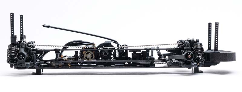
- Ride height when shock is fully extended
- Static/settled ride height
- Ride height when shock is fully compressed or chassis bottoms out
Observations... So some of you may have noticed that I was quite the droop skeptic before educating myself and talking a bit about it with others. Not anymore! I've seen it work with my own eyes! My truck handles so much better now! COG - Your center of gravity is now lower. Self Balancing - So we're 60/40 compression to droop now. What does that mean exactly and what does it do? This is the coolest part that I observed! When you ride up onto an obstacle with your left front tire (driver side) the obstacle will begin using the compression of your shock. When that 60% compression is used up by the obstacle your passenger side shock will begin to extend! That extension is from the droop and your suspension geometry that is all connected by the axle. When the low side (passenger side) extends (by around 40% of the shock travel) it actually levels the truck's chassis out. Traction - You'll be amazed at what your truck is able to traverse with the ability to step down/break the ridge/etc. coming over an obstacle (shock extension) to get grip! That just wasn't possible when you were at 100% compression because your shock couldn't extend before. Instead of extending then balancing you would just roll over to the low side.

DadCanyoufix?

EeePee said: I remember when we said droop, we were talking about shocks fully compressed with springs inside, under the pistons... And sag was the word we used referring to what you're calling droop. View attachment 320475 ... the good old days... Click to expand...
That was called semi droop cause it still has a spring keeping it up. Or 50/50 or 60/40. Droop, semi droop or not at all, I guess. I started messing around with that mid 2007 with a TLT . We had no idea what we were doing.
DowntownScience said: If one side can't compress then the other side can't droop...right? Is it more of a Comp. Crawler thing instead of a scaler thing? Click to expand...
Dad said: Like this? View attachment 320476 Click to expand...
EeePee said: All the shocks do is extend, there's no compression at all. I suppose it's more of a comp thing though I've seen it plenty of times on scalers, but it doesn't make much sense to me. Click to expand...
DowntownScience said: That could work too. I see you not only have spring below but also above the piston. Is that really the true full diameter of that piston? Click to expand...
Yubacitycrawler
- Jun 12, 2015
I run boom racing boomerang droop shocks, and love them, like he stated though there are pros and cons! The stock shocks are a good way to go if you don't want to mess with anything.
TacoCrawler
I wanna be dave.
Static ride height must first be determined and that static result is established by the 60/40 travel split. Droop is simply the distance of travel the axle will drop (extend lower), below the chassis's established static ride height, allowing the shocks their full extension. (40/60) While compression is the distance of the axle's upwards travel, above the chassis's static ride height allowing the shocks to compress upwards fully. (60/40) Solely lowering your suspension is not droop. It's simply lowering the chassis COG It's how it is with 1:1 rigs... why should rc crawlers be any different ? One can run a crawler without any springs at all, if they wanted. That set up would be considered all droop and offer no compression. Friend of mine does that... but crawls considerably slower then most. If yer gonna hammer down or bash some... some established compression is a must. My 1:1 rig rolls fairly close to 60/40 But RC crawlers don't have living occupants... so 50/50 works better for me.

Quarry Creeper
- Nov 11, 2015
In the motorcycle world this is referred to sag. On a dirt bike sag is 100-110mm on a 12" shock or 25% static sag. This is likely a good setting for fast rigs like a Yeti I imagine. Crawlers need a softer setup so I guess that is where the 40% comes in.

Nice read... for my wraith/deadbolt/ and wroncho I like 40/60 with light springs and heavy weight oil to slow the shock down. I also have my shocks slanted inward to the center of my rig. This does decrease the reach of the tire. Wroncho numbers Extended 3.75 Static 3.0 Comp. 2.5 .75 divided by 1.25 = 60% Crawls great.

AnimalHippie
- May 22, 2018
Thanks DowntownScience for posting this info! It was extremely helpful! Have a great day!
Similar threads
- Jan 26, 2024
- General Crawlers
- Jul 15, 2024
- Axial SCX10 III
- Mar 21, 2024
- Non Crawler RC's
- Jul 4, 2023
- Newbie General
- Jun 22, 2024
- Micro Scale Rigs
Motors & Man Stuff
The Home of all Your Manswers!
Suspension Travel and Motion Ratio: Explained
- Motorsport Tuning Guides
If you’re into motorsport or have a passion for cars, you’ve likely heard the term “suspension travel” before. But what does it actually mean, and how does it affect your car’s performance? In this article, we’ll delve into suspension travel and its relationship with motion ratio, which is crucial for a proper understanding of suspension setups.
Understanding Suspension Travel
Factors affecting suspension travel, suspension travel in different applications, compression vs. rebound travel, understanding motion ratio, the importance of wheel rate, q: what is suspension travel, q: how does suspension travel affect a car’s performance, q: what is motion ratio, q: what is wheel rate.
Simply put, suspension travel refers to how far a component of the suspension can move over the full extent of its movement range. In most cases, we’re interested in the vertical wheel travel, which is the distance that the wheel can travel from full droop to full compression. However, suspension travel can also refer to any other part of the suspension we might be interested in.
There are many factors that go into deciding how much suspension travel we need. Two of the most important and interrelated ones are the required stiffness of the suspension we’re working with and the roughness of the surface that the vehicle is running on. These factors will be discussed in detail later in the course.
The required suspension travel varies greatly depending on the application. For instance, a stadium truck running on rough terrain needs a large amount of vertical wheel travel to absorb the energy of a landing and reduce the forces involved. On the other hand, a high downforce single-seater running on a smooth surface requires less travel to keep things like camber, caster, and toe within suitable limits as the car negotiates the circuit.
Another important aspect of suspension travel is how much of the travel is available in compression versus rebound. A sensible starting point is to allow for approximately 2/3 of the available travel in compression and 1/3 in rebound. Having the majority of our suspension travel available on compression allows the suspension to absorb undulations in the road surface, while the rebound travel is there to keep the tires in contact with the road as the chassis heaves, rolls, and pitches.
Motion ratio is closely related to suspension travel and describes how much one component moves relative to the other when they’re linked together. We’re interested in the motion ratio between a number of different elements, but the most common is between the wheel and spring and damper assembly. In almost all cases, this ratio will not be 1:1, and the value of the motion ratio will generally vary as the suspension moves through its travel.
When comparing spring rates between different cars, it’s important to understand that the motion ratio between the wheel and the spring isn’t identical. We care about the effective spring rate at the wheel, which is generally referred to as the wheel rate. By using the motion ratio, we can calculate the wheel rate so we can make more relevant comparisons between cars with different suspension systems.
A: Suspension travel refers to how far a component of the suspension can move over the full extent of its movement range.
A: Suspension travel affects a car’s performance by absorbing energy, reducing forces, and keeping the tires in contact with the road.
A: Motion ratio describes how much one component moves relative to the other when they’re linked together.
A: Wheel rate is the effective spring rate at the wheel, which takes into account the motion ratio between the wheel and the spring.
In conclusion, suspension travel and motion ratio are crucial aspects of suspension design and tuning that can greatly affect a car’s performance. The required suspension travel varies depending on the application, and a proper understanding of motion ratio is necessary for comparing spring rates between different cars. By optimizing suspension travel and motion ratio, you can improve your car’s handling and performance on the road or track.
- Suspension Travel: What Is It and How Does It Affect Your Car’s Performance? – https://www.autosimple.com/suspension-travel-what-is-it-and-how-does-it-affect-your-cars-performance/
- The Importance of Motion Ratio in Suspension Design – https://www.nolimitmotorsport.com/blog/the-importance-of-motion-ratio-in-suspension-design/
- How to Calculate Wheel Rate: A Simple Guide for Racing Suspension – https://www.speedwaymotors.com/the-toolbox/how-to-calculate-wheel-rate/31488
Related Stories
Unlocking the power of the c8 corvette: proven bolt-on power adders, boosting your c8 corvette: a comprehensive guide to superchargers and turbochargers, breaking records: the c8 corvette’s best 1/4 mile times.
View all articles

How Much Shock Travel Do I Need?
Shock travel: You need it, but how much and why? Ultimately, it comes down to how you’re using your vehicle. A trophy truck with crazy long travel suspension designed to soak up canyons at 100 mph will have a very different answer than an autocross car that’s sucked down to the ground.
For the sake of today’s explanation, we’re going to stick to general street cars . That means you’re using your vehicle to cruise down roads that have imperfections, railroad tracks, and speed bumps ... not dedicated track cars that live on the autocross, drag strip or road course. Those vehicles may require very different answers based on a number of factors, from aerodynamics to tire size and track surface.
WHAT IS SHOCK TRAVEL?
Shock travel measures a shock’s movement through both compression and extension strokes. Compression means the shock’s piston rod is pushing up into the body of the shock, shortening (or compressing) in length. Extension is the exact opposite, meaning the piston rod is being pulled out of the body. This lengthens (or extends) the shock’s overall length.
Ultimately, you want enough travel in your shock not to top it out or bottom it out. Your shock should never be fully extended or compressed through your suspension’s full range of movement. What happens if it does? Nothing good. Not only will it give your car a rough ride, but a shock that does not have enough travel can cause performance issues and even damage your shocks or other suspension components.
HOW MUCH SHOCK TRAVEL DOES A STREET CAR NEED?

This depends on what type of suspension you have. It differs between straight axle suspensions and independent suspensions.
On straight axle suspension systems there is a 1:1 ratio between the movement of your shock and your wheel. That means if your wheel moves one inch, your shock extends or compresses one inch. In these applications 2.5 inches of shock travel in both directions (compression and extension) should generally be enough.
Depending on the way your suspension is set up, you may need more. If you want to limit body roll for stiffer handling, you may want less travel than that. But even in these cases, your shock should not be thing limiting your suspension—ie being fully extended to keep the car from experiencing body roll.
For independent suspension systems, shocks do not require as much travel. That’s because the control arm acts as a lever. So, while your shock may only be moving an inch, your wheel could be traveling two inches. It could be moving 3 inches. It all depends on where your lower shock is located. The closer your shock is to your wheel, the closer to 1:1 that motion ratio will be.
When measuring for shock travel on an independent suspension system, start with wheel travel. Make sure it can move 2.5 inches in both directions. To check this, measure between your upper and lower shock mount when your suspension is fully compressed and at full droop. This will tell you how much overall stroke you’ll need to keep from bottoming out or topping out your shock.

SHOCK TRAVEL FAQs
What if i’m building a custom suspension setup.
When setting up your own shock mounts, make sure you have a range of motion that allows enough travel. Just as importantly, make sure you can find and fit a shock that provides that much travel when extended and compressed. Any time you’re adding length, you’re adding stroke to the shock – meaning the shock will have a larger body. Browse QA1 custom mount coilover shocks.
How much shock stroke do I need for a street car?
For straight axle applications, most cars will require a shock with 5 inches of stroke or so. This allows for the 2.5 inches of compression travel and 2.5 inches of extension travel mentioned above. Independent suspensions will vary depending on their design. Use the method mentioned above to measure your shock amounts and find out how much stroke is required.
BRINGING IT ALL TOGETHER
We hope this helps answer some of the questions you might have about shock travel. Looking to find the right shock for your car or truck? Our tech team is happy to help. Give us a call at 952-985-5675.
- #Blog Content
- #Suspension Tuning
- #Troubleshooting
Recent Blog Posts
© Copyright 2024 QA1. All Rights Reserved
- Submit News
- Contact CompetitionX
CompetitionX CompetitionX is the most up-to-date source for RC Car News, Reviews and Videos for Radio Control. We also have the most comprehensive Manual Database on the web.
Rc suspension tuning guide – droop.
Tony Phalen March 23, 2023 RC Tuning Guide 3,334 Views
What is Droop? Droop is the amount of down-travel a suspension arm has. Droop can be set independently from front to back, but should be the same (normally) from side to side.
There are a couple different ways to measure droop, so make sure that you find one that works for you and stay consistent with your measuring.
Also, asking others what their Droop is is often a mute point – that number will only work if the both of you measure Droop the same way.
See also: Ride Height
Tuning with Droop – Front Less Droop • Less weight transfer to rear while accelerating • More aggressive steering • Less on-power steering • Less traction rolling • More stable at high speeds • Best for smooth tracks
More Droop • More weight transfer to rear while accelerating • Less aggressive steering • More on-power steering • Less stable at high speeds
Tuning with Droop – Rear Less Droop • Less weight transfer to front under braking • Less stable over bumps • More stable under braking
More Droop • More weight transfer to front under braking • More stable over bumps • Less stable under braking
Back to the RC Suspension Tuning Guide .
About Tony Phalen

Related Articles
Rc quick setup guide.
March 30, 2023
RC Suspension Tuning Guide – Wheelbase
Rc suspension tuning guide – body position, jconcepts choppers pre-mounted monster truck tires | competitionx.
JConcepts Choppers Monster Truck Tires are now available pre-mounted! Yes, these crazy-cool tires now come …
RC Car Droop: What It Is and How to Set It Up

Droop is an important part of suspension tuning, which is not really an exact science and also not a simple thing to do. You need to perform many adjustments and you need to learn your car’s technical specification very well in order to achieve higher performance on the race track.
Droop is the amount of down travel a suspension arm has and it can be set independently from front to rear and it should be the same from side to side. It is not actually a setting, but an attribute, because it is affected by the other settings you make on your suspension. Droop can allow or limit the weight transfer from one side to another, thus altering handling and control of your RC car. As we said above, it is not an exact science, because it differs greatly depending on your RC car model, on the track’s surface type or driving style. If you have set your droop correctly, you will be able to pass safely and without problems over bumps, holes and you will handle corners very well.
So you can you tune this setting? Typically, less droop means less body roll. Less front droop can reduce the upward travel on acceleration and it improves high-speed steering ability. This setting is also better on high-speed smooth tracks. However, more front droop does basically the opposite: it increases front chassis upward travel on acceleration and reduces high-speed steering ability. This setting is better on rough tracks
Now, let’s move on to rear droop tuning. Less rear droop can reduce rear chassis upward travel under braking or off-throttle conditions and improves stability during braking. Like less front droop, it is also better on high-speed smooth tracks. Increased rear droop help with increasing chassis upward travel during braking or off-throttle conditions and improves steering in slow corners. As well as the increased rear front droop, it is helpful in off-road tracks, as well as in bumpy conditions.
RELATED ARTICLES MORE FROM AUTHOR
Rc excavators – hydraulic cat digger & caterpillar models, nitro rc exhaust pipe: how to upgrade it – useful tips, rc car axle: how to tune it – useful tips, leave a reply cancel reply.
Save my name, email, and website in this browser for the next time I comment.
About droop & downstop

Droop measures how far down the car’s suspension arms are able to travel, or specifically the difference between the car’s natural ride height and its maximum ride height when the wheels just lose contact with the ground.
There are, however, a variety of ways that people actually measure droop. Common methods are (all taken with the car's wheels off the ground):
- Distance between the bottom of the chassis and the bottom of the wheel nut (shown in the diagram above)
- Distance between the bottom of the chassis and the bottom of the hub (shown in diagram below)
- Distance between the center of the shock’s two mounting screws (this is more accurately described as "shock length", but in some types of racing it is called droop and is a good substitute for the other measures.
Droop is sometimes changed via internal shock limiters (which control stroke ) or on some cars via specific downstop adjustments that limit how far down the arms can travel..
Droop allows (or limits) weight transfer from one side of the car to the other, or the front to the back.
Please note, changes to the car’s ride height will also change its droop if no other adjustments are made.
Downstop is a setting that controls how far down the suspension arms can travel. It is not the same thing as droop, although many racers use the two terms interchangeably.

What is the difference between downstop and droop?
Droop is a measurement of the suspension geometry. Droop is set via changes to the downstop or the shock's stroke , just like ride height is a measurement that is set via adjustments to shock pre-load.
Less droop
- Faster steering response
- Fewer traction rolls
- Generally suitable for smooth tracks
- Slower steering response
- Better handling over bumps
- Better jump landings
Front droop
Less front droop
- Less weight transfer to the rear during acceleration
- Less on-power steering
- More high-speed steering stability
More front droop
- More weight transfer to the rear during acceleration
- More on-power steering
- Less high-speed steering stability
Less rear droop
- Less weight transfer to front during braking
- Less stability over bumps
- More stability under braking
More rear droop
- More weight transfer to front during braking
- Less stability under braking

1/8 Off-road
1/10 Off-road
Short Course Truck
How to Measure Droop on Off-road RC Cars
Mayako's David Ronnenfalk demonstrates two different ways of measuring droop on off-road RC race cars, so you can choose which works best for you.

Small-scale Off-road
Small-scale On-road
Weight transfer - RC Handling Guides
What does weight transfer (or load transfer) do to the handling of an RC car? Is it good or bad?

Chassis roll - RC Handling Guides
Is it good or bad when your car's chassis rolls? It depends...

Ultimate RC Setup Troubleshooting Guide
How to fix understeer (push), oversteer (loose), and other common handling problems for both on-road and off-road RC cars.
Related settings
New on sd: , rc car deals page.
.jpeg)
Popular topics
So dialed apps, for ios & android.

RC Setup App & Race Log

RC Gear Calculator Pro

RC Speed Run

RC Gear Recommender

RC Speed Calculator Pro

RC Pill Insert Calculator
RC Fuel Mileage Calculator
%20copy.avif "suspension travel droop")
RC Rock Crawl Scorekeeper


Suspension 101: Droop – Measuring & Adjusting Suspension Droop
PARDON THE INTERRUPTION
Purchase options.
For the Ultimate RC’er. You will have access to advertising free daily-curated RC content written by the best writers in the game bringing you entertainment and information all in one place. You get to enjoy product reviews and builds before anyone else in the world. You also gain full access to the digital edition of RC Car Action and all the archives. If that’s not enough, during the month you receive exclusive industry offers saving you money, making an annual Boost Membership more than worth it.

- Membership Login

Forgot your password?
Lost your password? Please enter your email address. You will receive mail with link to set new password.
Back to login
- Tutos & Blog
- Just arrived
- 1/28 Mini-Z
- Other scales
- MP10e Readyset
- Optima Mid Legendary Series
- MP9E EVO Readyset
- Inferno Neo 3.0 Nitro
- Ultima Legendary Series
- MP9E Evo Readyset
- MP9E EVO Race kit
- Accessories / Misc.
- Kits voitures Sparko
- F8 nitro 1/8 Formula eight
- F8e brushless Formula eight
- Sparko F8 Nitro option parts
- Accessories / Misc. Sparko
- B6.4 / B6.4D
- Kits voitures Hobbytech
- Pièces détachées Hobbytech
- Accessories | Cleaning
- Turbo Racing
- Funtek car Kits
- Parts / Accessories Funtek RC
- 8ight-X/XE 2.0
- 8ight-XT/XTE
- 22 5.0 ELITE
- 22 5.0 Buggy
- 22T Stadium Truck
- 8ight nitro
- 22 5.0 buggy
- Accessories
- Greases, lubricants and glue
- Nitro engines
- General accessories
- Electronic accessories
- Ball bearings
- Mylaps timing
- Speedos (ESC)
- Other accessories
- Highest RC servos
- Miscelaneous
- Pink Performance
- Spare parts
- Academy & Coaching
- Engine Break-In, Electronic Welding
- Pro RSRC Assembly Radio Controlled Car
- Options TRC Throttlefinger Racing Concept
- Accessoires
- Batteries / Cells
- 1/8 OFF-ROAD
- Goodies and options
- Kyosho MP10 TKI3
- Kyosho MP10e TKI2
- Kyosho MP10 TKI2
- Kyosho MP10
- Kyosho MP10e
- Kyosho MP10Te
- Kyosho MP10T
- Kyosho MP9E EVO
- TLR 8ight-X
- TLR 8ight-XE
- TLR 8ight 4.0 Nitro
- TLR 8ight-E 4.0
- TLR 8ight-T 4.0
- Helly Hansen WW
- Racing experience
- Glued tires
- Tires | Inserts | Wheels
- Accessories | Tools
- 1/8 buggy tires
- 1/8 Truggy tires
- 1/10 Buggy Tires and wheels
- Crawler and On-road tires
- Wheels and inserts
- Accessories / Other
- Mounted tyres
- Tyres / Wheels / Inserts
- Tires, wheels
- Tools, accessories
- Smart Workshop
- Spare parts for nitro engines
- Accessories, tools, misc.
- Hot deals & Stock Clearance
- RC carbon cavalieri
Search on blog
Quick tutorial #4: up and down travel, how to adjust it and what does it change.
Quick tutorials are a simple way to understand the settings of your car in a few minutes.
A subject, a short video, in order to answer 2 essential questions: WHY and HOW?
We talk about suspension travel, the length of possible travel of your RC car's suspension.
It is separated in 2, with up travel and down travel (droop).
The down travel corresponds to the maximum ground clearance ( see also the tutorial on ground clearance ) that your chassis may have.
That is to say the maximum lift your car can have before the wheels take off.
We can easily change this setup and we will see it later.
The up travel corresponds to the height of the wheel in relation to the chassis when the shock absorber is fully compressed.
It is generally limited to the geometry of the suspension and the shock absorber , and we don't really need to change it.
HOW TO CHANGE THE SETUP
Down travel (droop).
There are several ways to measure the value of your down travel.
The most used is measuring the length of the shock absorber when the car is placed on a base (usually with the wheels for the force applied to the suspension). We measure the distance between the top and the feet of the shock absorber, with a caliper or a special tool.

This technique is very quick and practical , however it is not very precise , because 0.5mm of difference on the shock absorber length can have a difference of a few millimeters at the wheel.
In addition, this value will also depend on the geometry of the car and the different positions of the shock absorber. Indeed, for a given measured shock length , if you use the inside or outside position on the wishbone, you will not have the same value of travel at the wheel at all.
This is also the case when switching from the MP10 to the MP10 TKI2 for example .
With the new shock mounts and long shocks we can go lower with more angle on the wishbone which is a big plus but for a given travel 102mm up front and 119mm out the rear on the MP10 , you will have roughly the same don travel as 105mm/122mm on a TKI2.
We would therefore prefer to use blocks, positioned under the chassis, then measure the value under the axle of the wheel. If you always set a given value, your actual wheel travel will therefore always be the same, regardless of the shock positions used.

In general for a 1/8 off-road buggy , the value is close to 30mm in front (0 with a 30mm block) and 25mm behind (-5 with a 30mm block).
To modify the value of the down travel (droop) you have to adjust the screw which is trapped in the suspension arm and in contact with the chassis plate.
The more you tighten the screw, the more you will reduce the droop and vice versa.
For 1/10 buggies, you must tighten or loosen the shock absorber ball end or insert washers on the rod below the piston (inside the shock absorber). The length of the rod coming out of the shock absorber will be measured before mounting it on the car.
For the up travel, this setting is often fixed by the engineers/developers because it depends on the geometry (length of the shock bodies, positions etc.) and it is not necessary for you to modify it.
However, to measure it, you have to place the car on a flat surface, chassis on the ground, and compress the suspension to the maximum. Then measure the value under the wheel axle.
To reduce this value, it will be necessary to place washers on the shock absorber rod between the body and the yoke outside of it.
WHAT DOES IT CHANGE ON THE TRACK ?
A car with more down travel will have more motion on the track. During acceleration/braking phases, but also left/right. The car will be less responsive and will change course slower.
Your car will therefore be less precise but easier to drive and much more efficient on r ough surfaces , with the wheel having more travel to stay in contact with the ground in bumps.
Same, with more droop, the wheel will hit the ground sooner over jumps and the suspension will have more time to absorb the landing. The landing will therefore be smoother.
When accelerating, the car will tend to pitch up more and when braking the rear axle will rise. This can give more roll to the front end and therefore more steering.
On tracks with off-cambers, we will choose a rather limited travel, the car being able to rise too much and lose its corner speed.
For up travel, the effects are pretty much the same.
To summarise:
- flat track and/or high grip, we reduce up and down travels.
- tracks with holes and/or low grip, we increase the up and down travels.
Travel values are really going to depend on the model you are using.
On my MP10 TKI2 the values I use for the front are 107mm in shock length 124mm for the rear.
For an original MP10e , we are rather around 102 mm in front and 118 mm in the back.
Please note that the value of the down travel tends to change often (hits on the chassis, torsion of the suspension, etc.), it is therefore advisable to check these values regularly.
See you soon in a new episode!
Reno Savoya
Share this content
Add a comment
Antispam protection : How many letters include "RSRC" ?
- 903-993-0000
- [email protected]
Glossary of suspension terms
Need help with your suspension terminology? We understand suspension can be complex and somewhat daunting at first. We created an in-depth list of suspension system terms and definitions to help.
Anti-dive is a suspension characteristic that affects the amount of suspension travel when the brakes are applied. When a car is decelerating due to braking there is a load transfer off the rear wheels and onto the front wheels. Vehicle properties such as the center of gravity height, total weight, deceleration rate and wheelbase affect the amount of dive a vehicle experiences. 100% anti-dive refers to no change in front suspension height under braking. This is achieved by adjusting the pivot points of the suspension system or through hydraulics in the front dampers.
Rear suspension kinematic characteristic which reduces the amount of pitch under braking forces. Street cars may have up to 150% anti-lift for driver comfort.
Anti-Roll Bar (aka: stabilizer bar, sway bar - from anti-sway bar)
A transverse torsion bar linking both sides of a suspension system with bushings mounted on the chassis that allow it to rotate freely. The bar's ends are connected to or shaped as lever arms, with attachments to the suspension linkages at each side via ball-joint links, rubber-bushed pivot links, or as on race cars, spherical rod ends called Heim joints. When both wheels take a bump equally, the wheels move the same amount without twisting the anti-roll bar. Individual wheel movement or body roll will force the bar to twist as the lever arms are moved, thereby adding the bar's own spring rate to that of the car's springs. Although an anti-roll bar's main function is to reduce body roll in cornering, it also influences overall handling. You can fine-tune Over- or Understeering Tendencies.
When a car is accelerating forward, there is a load transfer off the front wheels and onto the rear wheels. Vehicle properties such as the center of gravity height, total weight, acceleration rate and wheelbase affect the amount of squat a vehicle experiences. 100% anti-squat refers to no change in rear suspension height under acceleration. This is achieved by adjusting the pivot points of the suspension system or through hydraulics in the rear dampers.
The geometric center and innermost point of a turn or corner on a roadway or race course.
Description of handling characteristics of a vehicle, describing understeer, neutral, or oversteer.
Weight added to a vehicle usually to bring it to a minimum weight requirement-useful for adjusting balance in racing vehicles.
Torsional stiffness of the antiroll bar (or torsion bar), either at the drop links or at the wheel's contact patch. This is usually expressed in N/mm or lb/in.
Linkage component with a central pivot and multiple link attachment points. Usually used with inboard suspensions to transfer loads from the pull/push rod to the spring/damper. Technically, a rocker uses the same pivot for pullrod and damper, while a bell crank has different attachments for each.
Vertical movement of wheel towards chassis. Aka deflection, jounce. In racing, the terms "bump and droop" are used together to define suspension travel. For OEM" jounce and rebound".
Change in toe angle under bump/droop. Normally, slight toe-in with bump is used in the rear and slight toe-out with bump is used in the front to aid stability. Excessive bump steer in the front can be caused from incorrect angle of the steering tie-rods from excessive lowering.
The wheel angle relative to ground/chassis in front/rear view. Negative camber is when the tops of the wheels are closer together than the bottoms. Tuning the amount of negative camber can be very useful in achieving maximum grip in racing. Excessive negative camber can wear the inside edge of the tires under acceleration or braking and reduces grip. Not enough negative camber can wear the outside edge of the tire while cornering and reduces grip.
The caster angle identifies the forward or backward slope of a line drawn through the upper and lower steering pivot points when viewed directly from the side of the vehicle. Caster is positive if the line angles towards the rear of the vehicle at the top, negative if the line angles towards the front. Positive caster improves directional stability.
Center of Gravity (CoG)
The exact point around which an object, such as a vehicle, is perfectly balanced in every direction. It's the center point of the vehicles mass. The position of the center of gravity affects stability and handling: lower is usually more stable.
Centrifugal Force
The apparent force that draws a rotating body away from the center of rotation. Centrifugal force is not a true force; it is a form of inertia.
Chapman Strut
Named after Colin Chapman of Lotus Racing. It is basically a MacPherson type strut used in a rear suspension.
A term used to describe a type of spring.
When a spring is compressed to a point that the coils make contact. The spring has travelled to its maximum compressed height or at full block.
Coilover is short for "coil spring over shock". Consists of a shock absorber with a coil spring assembled together as one unit. Most coilovers have adjustable ride height using an adjustable spring perch.
Coil Spring
It's actually a torsion bar, wound into a helical shape. It's the Heart of the Suspension System carrying the car's weight under all static and dynamic conditions, absorbing the shocks from uneven roads and bumps, and correctly positioning all other suspension components. But it can provide only partial roll resistance as the Anti-Roll Bars provide additional support.
Compression
The displacement of sprung and unsprung masses in the suspension system in which the distance between the masses decreases from that at static condition. Compression damping is the primary factor in ride quality, road compliance and steering response.
Control Arm (aka: A-arm)
A hinged suspension link between the chassis and strut or wheel hub. A Double A-Arm suspension has upper and lower control arms. A control arm may also attach to a spring, damper, anti-roll bar and pull/push rod.
The ability of a vehicle to travel through a curved track or highway. Cornering force (side force) is the lateral force that will push the vehicle toward the outside of the corner while cornering.
Corner balancing (aka: corner weighting)
Optimizing the weight of the vehicle at each wheel to maximize the vehicles transitional response. Tire traction and suspension movements are determined by the force (weight) on each corner of the vehicle. Equal diagonal weighting provides the best transitional response while equal front weight provides the best braking response. Adjustable ride height coilovers allow easy fine tuning for maximum and balanced cornering performance without adding ballast.
Damper (aka: shock absorber)
A shock/strut used to dampen the kinetic energy of a spring and control rate of load transfer. All hydraulic dampers (shock absorbers) work by the principle of converting movement into thermal energy (heat). For that purpose, fluid in the damper is forced to flow through restricted holes and valve systems, thus generating hydraulic resistance. See also shock absorber.
Digressive damping
Digressive damping describes a style of damper valving. Digressive means that as damper shaft speed increases, damping forces increase at a decreasing rate. In comparison, a linear rate damper follows the same increasing path. This allows for sport dampers to offer more low speed control for performance handling without being overly harsh on rough roads or big bumps.
Dive (aka nose-dive)
Vehicle pitch under braking.
Double A-Arm
Independent suspension design with a short upper and long lower arm connecting chassis to suspension upright. Each arm is in the form of an A or V when viewed from above. Very common in racing; allows precise control of camber and roll center.
Double Wishbone
(aka: double a-arm)
Downforce (aka negative lift)
Downwards thrust created by the cars aerodynamics, typically through wings and spoilers. Additional downforce allows a car to corner faster by increasing the vertical force on the tires, which creates more grip.
Rebound (aka: droop)
Amount of down travel of a suspension system. In racing, the terms 'bump and droop" are used together to define suspension travel; automotive engineers call it "jounce and rebound".
Attach anti-roll bar to suspension arms, upright or strut. The name comes from the typical configuration: a link drops down from the anti-roll bar to the lower suspension arm.
Dynamic Weight Distribution
Weight distribution while driving under transient handling or aerodynamic forces.
Full Coil Suspension
A vehicle suspension system in which all four wheels have their own coil spring.
Gas-filled Shock Absorber (aka: gas shock or damper)
A shock that uses nitrogen gas, to pressurize the fluid in the shock to reduce or prevent aeration or foaming which can cause cavitation and loss of damping.
The amount of adhesion (traction)a tire has to the road.
Heavy-Duty Shock Absorber
Shock absorbers having reinforced seals, a mono-tube design to reduce heat build-up, and a rising rate valve for precise spring control.
Helper Spring
A very soft spring used in racing to prevent the Main Spring (or Main- and Tender Spring) from becoming loose in the spring seats, when the suspension is unloaded or at full droop.
Suspension spring system where the spring/damper is mounted near or within the chassis via rocker and pull/push rod system. Principal advantage is removing the spring/damper from the airstream, improving drag and downforce on ground effects cars (motorsport). Brake system where the disk and caliper are mounted on the sprung mass, via axles and CV joints. Principal advantage is reducing unsprung mass. (motorsport)
Independent Suspension
Any suspension which is not a solid axle type. This allows each wheel to move vertically (reacting to bumps or road irregularities) independently form each other.
Instant Center
The wheel and tire motion is constrained by the suspension links on the vehicle, the motion of the wheel package in the front view will scribe an imaginary arc with an "instantaneous center" of rotation at any given point along its path. The instant center for any wheel package can be found by following imaginary lines drawn through the suspension links to their intersection point.
Vertical force applied on chassis under cornering. This force can lift the vehicle if the roll center is above ground or drop if underground. Susceptible with swing axle suspension design. Typically, jacking will cause a slight increase in ride height and slight loss of camber while cornering, which results in loss of grip.
Jacking Down
Temporary lowering of chassis on bumpy roads due to excessive rebound damping.
Jounce (aka bump)
The upward travel or compression of the spring and shock absorber.
Describes the motion characteristics of a suspension, as opposed to the force characteristics (motion ratios).
Kinetic Energy
The energy an object possesses due to motion.
Opposite of downforce.
To raise a vehicles ride height for additional ground clearance to increase off-road capability.
Linear-rate coil spring
A coil spring with equal spacing between the coils, one basic shape, and constant wire diameter having a constant deflection rate regardless of load.
Aka oversteer (motorsport, NASCAR).
Lowering (aka suspension lowering)
Lowering the vehicles CoG. The main goal in lowering a vehicles CoG with the suspension is to improve handling and stability (street performance and motorsport). As always there is a right way and a wrong way to lower a vehicle.
Yes/Right way: With a properly engineered lowering suspension kit, the components fit perfectly into the factory locations and maintain proper fitment from full droop to full jounce. The lower CoG benefits are many, both in performance and appearance:
Performance: reduced nose dive under braking, squat while accelerating and body roll when cornering. Also, with the reduced ride height there is another benefit that is often overlooked: better aerodynamics. Since less air goes underneath the vehicle (where most aerodynamic drag occurs) it requires less horsepower to move the vehicle forward. The results, better fuel efficiency and higher top speeds (motorsport). Appearance: The lower CoG and corresponding ride height reduces excessive fender-well clearance giving the vehicle a more aggressive stance: Traction + Attraction! No/Wrong way: Improper lowering (short springs, cut springs, heating springs) can be very dangerous; too low results in improper suspension arm angles causing severe bump steer, improper wheel alignment and the suspension and/or chassis bottoming out, which can all contribute to a complete loss of handling and control. Short or shortened springs can fall out of their spring seats at full droop, which can cause a severe accident. Heating the spring causes the spring to lose tensile strength and will cause the spring to fail and collapse very quickly. Lowering the wrong way can lead to catastrophic results and a much bigger expense in repairs to get it corrected.
MacPherson Strut
Type of car suspension system which uses the top of a telescopic damper as the upper steering pivot. It is widely used in the front suspension of modern vehicles and is named for Earle S. MacPherson, who developed the design.
Inboard suspension system which is actuated by both left and right wheels to a single spring/damper. All roll resistance is then carried by the antiroll bar. (motorsport - Formula series).
Motion Ratio
The difference of motion on a vehicles suspension spring and shock travel for a given amount of wheel travel. If the spring is half the distance from the control arm pivot as the wheel, the motion ratio relative to the wheel is 1 to 2.
Multilink Suspension
Common on independent suspension systems, using three or more lateral arms instead of only one upper and lower control arm per corner.
Handling characteristic between understeer and oversteer. This is usually the goal of chassis tuning, with a slight bias towards over or under-steer depending on track conditions and driver preference (motorsport).
Lateral distance between a wheel's vertical centerline and hub face. Positive offset has wheel center line further outboard than hub face; generally found on front wheel drive vehicles and newer rear wheel drive vehicles. Improper offset can negatively affect the handling of a vehicle.
Outboard Suspension
Traditional suspension system where the spring/damper is mounted directly between the chassis and lower/upper arm or upright.
The lengths of a vehicle, either front and rear, which extend beyond the wheelbase.
Vehicle handling characteristic that occurs when a car turns (steers) by more than (over) the amount commanded by the driver. Therefore, the rear wheels tend to lose traction before the front.
Percent Slip
Amount of longitudinal (accel. & braking) slip between the tire and the road. This is expressed as the ratio of the velocity of slipping to the CL wheel velocity. As with slip angle, there is an optimum percent slip for maximum grip, beyond which the tire spins. (Motorsports).
Viewed from the side, the change in vehicle angle with respect to the ground. For example, in braking, weight is transferred from the rear to the front, causing unloading of rear springs and additional load on the front springs, resulting in nose dive. The effect may be reduced or eliminated with anti-pitch suspension geometry, lower CoG, longer wheelbase or higher spring rates.
Polar Moment of Inertia
The resistance of an object to rotational acceleration. When the mass of an object is distributed far from its axis of rotation, the object is said to have a high polar moment of inertia. When the mass distribution is close to the axis of rotation, it has a low polar moment of inertia. A mid-engine car has most of its mass within its wheelbase, contributing to a low polar moment of inertia, which, in turn, improves cornering turn-in.
Pre-Setting (aka Blocking)
A complex production technology. Most suspension springs go through the Pre-Setting process. Designed to expand the stress levels to higher limits each spring is compressed to full block, meaning all coils make contact under pressure. This allows new engineering limits to design superior products and to make springs permanently block-resistantÑno more sagging! All product design characteristics will now be maintained for the life of the spring, unless damaged; physically or by corrosion.
Progressive-rate spring
A spring system that increases in spring rate with increase in deflection/travel.
Inboard suspension component which place the spring/damper unit inboard and out of the air stream to further reduce air resistance. The pull rod typically attaches near the upper ball joint and pulls on the inboard rocker when in bump. Pull-rod designs often have somewhat lower and more non-linear motion ratios due to packaging of the rocker next to the ground, which allowed the designers to put more components close to the car's floor, lowering its center of gravity. (Motorsport)
Aka understeer (motorsport & NASCAR).
Inboard suspension component which place the spring/damper unit inboard and out of the air stream to further reduce air resistance. The push rod typically attaches near the lower ball joint and pushes on the inboard rocker when in bump. Push-rods may be preferred to pull-rods for more adjustability with higher and more linear motion ratios, however may introduce buckling concerns. (Motorsport)
The wheel and suspension go back down away from the chassis. The main function of rebound in a damper (shock absorber) is to control the speed by which the suspension travels during reboundÑcontrolling the spring rate on the car. Rebound damping also provides the roll control of the vehicle.
Rising Rate
A suspension system where the spring rate increases when the wheels move further into jounce. This action can be accomplished by configuring the geometric shape of the suspension, by using progressive rate springs which change tension as they are compressed, or by using two or more springs with rubber stops. The purpose of a rising-rate suspension is to maintain consistent ride and handling characteristics under a variety of situations: loaded or unloaded, straight roads or curves, and smooth roads or bumpy.
Road Holding
The ability of a vehicle to maintain contact with the road surface under all conditions. The constant contact of the tires to the ground is crucial for the vehicle to steer, brake and accelerate.
Road Isolation
The vehicle's ability to absorb shocks from irregular road surfaces and keep them from the passenger compartment.
Inboard suspension component used to transfer wheel loads to the spring. The rocker may be either an entire suspension control arm (usually the upper arm) or a component between the pull/push rod and spring.
A line that connects the front and rear roll centers. If the axis runs nose-down, the car tends to oversteer. If the axis runs nose-up, the car tends to understeer.
Roll Center
The theoretical point around which the chassis rolls, and is determined by the design of the suspension. Front and rear suspensions have different roll centers. The amount that a chassis rolls in a corner depends on the position of the roll axis relative to the car's center-of-gravity (CoG). The closer the roll axis is to the center of gravity, the less the chassis will roll in a corner.
Roll Couple Distribution (RCD)
The ratio of weight transfer of the front and rear wheels, usually expressed as a percentage. The roll couple percentage is a simplified method of describing lateral load transfer distribution front to rear, and subsequently handling balance. It is the effective wheel rate, in roll, of each axle of the vehicle as a ratio of the vehicle's total roll rate. It is commonly adjusted through the use of anti-roll bars, but can also be changed through the use of different spring rates.
Roll Flexibility
Expressed as degrees of chassis roll per G of lateral acceleration. Street cars range between 2.5' and 6'. Most race cars 0.3' - 0.8' (ground effects cars essentially do not roll -- below 0.1' is common). Excessive roll stiffness degrades handling on bumpy circuits. Insufficient roll stiffness reduces transient response and tire grip.
Roll Moment
The roll moment is the product of the sprung mass and the square of the distance between the vehicle's roll center and its center of mass. If the vehicle is subjected to centrifugal forces, such as in a turn, the roll moment will cause the body to rotate (lean) towards the outside of the turn. Together with the roll stiffness, this factor determines the roll flexibility.
Roll rate is similar to a vehicle's ride rate, but for actions that include lateral accelerations, causing a vehicle's sprung mass to roll about its roll axis. It is expressed as torque per degree of roll of the vehicle sprung mass. It is influenced by factors including but not limited to vehicle sprung mass, track width, CG height, spring and damper rates, roll center heights of front and rear, anti-roll bar stiffness and tire pressure/construction. The roll rate of a vehicle can, and usually does differ front to rear, which allows for the tuning ability of a vehicle for transient and steady state handling. The roll rate of a vehicle does not change the total amount of weight transfer on the vehicle, but shifts the speed at which and percentage of weight transferred on a particular axle to another axle through the vehicle chassis. Generally, the higher the roll rate on an axle of a vehicle, the faster and higher percentage the weight transfer on that axle.
Roll Stiffness
The resistance to chassis roll from the springs, anti-roll bars or both. Together with the roll moment, the total roll stiffness of the vehicle affects the roll flexibility.
Lateral displacement of the wheel centerline in bump/droop due to an instant center above or below ground. Suspension design should keep scrub to a minimum to reduce unwanted side loads generated during a bump. Scrub is not the same as "scrub radius".
Scrub Radius
The distance in front view between the steering axis and the center of the contact patch of the wheel, where both would theoretically touch the road. If these lines intersect at the road surface, a zero scrub radius would be present. When the intersection is below the surface of the road, this is positive scrub radius. Conversely, when the lines intersect above the road, negative scrub radius is present. The point where the steering axis line contacts the road is the fulcrum pivot point on which the tire is turned. Scrub radius is changed whenever there is a change in wheel offset as on the tyre line where the wheels are pushed outboard causing scrub radius to become more (+). Older cars tended to have very close to zero scrub radius but often on the (+) side, newer cars with ABS all have negative scrub radius (that's why all the newer cars have the wheels offset more inboard).
Section Height
The sidewall distance from the wheel rim to the unloaded tread surface. A low section height improves transient response; a high section height improves ride quality.
Section Width
Maximum width of an unloaded tire. Wider is normally better for grip, though excess width may result in insufficient tire temperatures and unnecessary unsprung weight.
Short-Long-Arm
Any independent suspension system with short upper arms and long lower arms (double a-arm, multi-link).
Single Wheel Bump Rate
Vertical wheel travel spring rate when only one wheel hits a bump. When this occurs the anti-roll bar does alter the spring rate. What happens is that the anti-roll bar twists as the wheel is raisedÑsince the other wheel does not move. The bar twists over its whole length adding this spring rate to the suspension spring rate.
A circular area of flat pavement used for various tests of a car's handling. The most common skidpad use is testing lateral acceleration, measured in g-force.
Referring to tiresÑthe indirect measure of the fraction of the contact patch that is sticking.
The angle between a rolling wheel's actual direction of travel and the direction towards which it is pointing. Tire grip increases with slip angle until a certain point, at which the tire starts to skid.
Suspension where left and right wheels are rigidly connected. They are nearly universally used in heavy-duty trucks and most light and medium duty pickup trucks, SUVs, and vans. Still used in motorsport: circle track, Trans Am and off-road.
A mechanical device, which is typically used to store energy due to resilience and subsequently release it, to absorb shock, or to maintain a force between contacting surfaces. They are made of an elastic material formed into the shape of which returns to its natural length when unloaded. Springs come in various forms: helical coil, torsion beam, leaf (semi-elliptical), rubber (polyurethane) bushing and air bag. The helical coil spring are most commonly used in street performance vehicles and motorsport. The other spring types are nearly universally used in heavy-duty trucks and most light and medium duty pickup trucks, SUVs, and vans.
Spring Rate
The spring rate (or suspension rate) is a component in setting the vehicle's ride height or its location in the suspension stroke. When a spring is compressed or stretched, the force it exerts is proportional to its change in length. The spring rate or spring constant of a spring is the change in the force it exerts, divided by the change in deflection of the spring. Vehicles which carry heavy loads will often have heavier springs to compensate for the additional weight that would otherwise collapse a vehicle to the bottom of its travel (stroke). Heavier springs are also used in performance applications where the loading conditions experienced are more extreme. Springs that are too hard or too soft cause the suspension to become ineffective because they fail to properly isolate the vehicle from the road. Vehicles that commonly experience suspension loads heavier than normal have heavy or hard springs with a spring rate close to the upper limit for that vehicle's weight. This allows the vehicle to perform properly under a heavy load when control is limited by the inertia of the load. Riding in an empty truck used for carrying loads can be uncomfortable for passengers because of its high spring rate relative to the weight of the vehicle. A race car would also be described as having heavy springs and would also be uncomfortably bumpy. However, even though we say they both have heavy springs, the actual spring rates for a 2,000 lb (910 kg) race car and a 10,000 lb (4,500 kg) truck are very different. A luxury car, taxi, or passenger bus would be described as having soft springs. Vehicles with worn out or damaged springs ride lower to the ground which reduces the overall amount of compression available to the suspension and increases the amount of body lean. Performance vehicles require different spring characteristic than average vehicles.
Spring Sag (aka: sagging)
The loss of spring load and length caused by a poor design, insufficient material or excessive loading beyond its physical limits. Over time, this can cause the spring to collapse or even break. There is a stress limit even for the best materials, but the max allowed stress levels are then superior. But even those high stress levels can be expanded by special production technologies - see Pre-Setting (aka: Blocking).
Sprung Mass
In a vehicle with a suspension, sprung mass (or sprung weight) is the portion of the vehicle's total mass that is supported above the suspension, including in most applications approximately half of the weight of the suspension itself. The sprung weight typically includes the body, frame, the internal components, passengers, and cargo.
Vehicle pitch under acceleration.
Stabilizer Bar
see anti-roll bar.
Static Weight Distribution
Static weight distribution is the weight resting on each tire contact patch with the car at rest, exactly the way it will be driven or raced (with driver Ð motorsport).
Steering Arm
Lever arm rigidly attached to upright or hub, which is connected to the tie rod. Steering arm and tie rod placement define the Ackerman steering system.
Static friction, usually referring to suspension, is friction that needs to be overcome to enable the motion of stationary objects. Higher stiction in a suspension, may lead to unpredictable chassis heights and poor handling.
The term given to the system of springs, shock absorbers and linkages that connects a vehicle to its wheels and allows relative motion between the two. Suspension systems serve a dual purpose & contributing to the vehicle's road holding/handling and braking for good active safety and driving pleasure, and keeping vehicle occupants comfortable and reasonably well isolated from road noise, bumps, and vibrations, etc. These goals are generally at odds, so the tuning of suspensions involves finding the right compromise. It is important for the suspension to keep the wheel in contact with the road surface as much as possible, because all the road or ground forces acting on the vehicle do so through the contact patches of the tires. The suspension also protects the vehicle itself and any cargo or luggage from damage and wear. The design of front and rear suspension of a car may be different.
See anti-roll bar.
Simple independent suspension of 1 lateral link rigidly connected to the wheel (early VW Beetle). With this design, wheel camber changes radically through the suspension stroke.
Tender Spring
Linear or progressive Tender Springs combined with Main springs provide a dual or multi-stage Suspension characteristic with a softer initial rate and a firmer final rate.
Tire Compound
A mix of materials that goes into making a tire. For performance and motorsport it's mainly about the hardness of rubber - softer is stickier, harder lasts longer.
The symmetric angle that each wheel makes with the longitudinal axis of the vehicle. Positive toe, or toe in, is the front of the wheel pointing in towards the centerline of the vehicle. Negative toe, or toe out, is the front of the wheel pointing away from the centerline of the vehicle. Toe can be measured in linear units, at the front of the tire, or as an angular deflection. Front wheels that toe-out slightly is preferred for turning response and toe-in for rear wheels adds stability.
Triangulation
In chassis design to prevent flex. Geometric configuration of chassis tube members. By adding a diagonal member, connected corners are held at a fixed distance. They can't be spread apart or moved closer together. Despite pivots for corners, the structure cannot be forced out of shape, and is therefore rigid. The additional member to a four-sided structure forms two triangles in the structure. This is called triangulation.
Suspension and chassis adjustments to optimize handling.
Understeer (aka: push)
Vehicle handling characteristic when a car steers less than (under) the amount commanded by the driver, meaning the front wheels tend to lose traction before the rear.
Unsprung Mass
The mass of the suspension, outboard brakes, wheels and other components directly connected to them, rather than supported by the suspension. The unsprung weight of a wheel controls a trade-off between a wheel's bump-following ability and its vibration isolation. Bumps and surface imperfections in the road cause tire compressionÑwhich induces a force on the unsprung weight. The unsprung weight then responds to this force with movement of its own. The amount of movement, for short bumps, is inversely proportional to the weight - a lighter wheel which readily moves in response to road bumps will have more grip and more constant grip when tracking over an imperfect road. In contrast, a heavier wheel which moves less will not absorb as much vibration; the irregularities of the road surface will transfer to the cabin through the geometry of the suspension and hence ride quality and road noise are deteriorated. For longer bumps that the wheels follow, greater unsprung mass causes more energy to be absorbed by the wheels and makes the ride worse.
Weight Distribution
See static weight distribution.
Wheel Frequency
Square root of (wheel rate/sprung mass carried by wheel). A characteristic of suspension stiffness that may be used to compare cars of different weights. Race cars typically have higher front frequencies than rear to reduce dive and improve traction; street cars are the opposite for "flat ride" over bumps.
Wheel rate is the effective spring rate when measured at the wheel. This is as opposed to simply measuring the spring rate alone. Wheel rate is usually equal to or considerably less than the spring rate since springs are mounted on control arms, swing arms or some other pivoting suspension member. Wheel rates are usually summed and compared with the sprung mass of a vehicle to create a "ride rate" and corresponding suspension natural frequency in ride (also referred to as "heave"). This can be useful in creating a metric for suspension stiffness and travel requirements for a vehicle.
The distance between the centers of the front and rear wheels. Longer wheelbase improves stability, shorter wheelbase improves maneuverability.
The angle between vehicle centerline and actual direction of motion around a turn. (oversteer/understeer).

Lamborghini Unveils the Revolutionary Temerario: A New Era in Hybrid Supercars
Lamborghini has unveiled its latest model, the Lamborghini...

Acura Unveils Integra Type S HRC Prototype: A Track-Inspired Marvel
In a bold move to solidify its presence...

Why Wheel Alignment is Crucial After Installing a New Suspension
Upgrading your car's suspension can dramatically enhance its...

How to Prepare Your Car for Car Shows: Suspension Tips for a Show-Stopping Ride
Car shows are the ultimate showcase for automotive...

Springrates Now Carries Eibach's Full Product Line!
We're thrilled to announce a significant expansion in...
Shop Our Store
shop by category

Lowering Springs

Air Ride Kits

Universal Air Cups
Shopping Cart
Spend $250.00 more and get free shipping!
Too soon, Junior.
Order Comments:
ACCOUNT LOGIN
Enter your email and password to access your account.
RESET YOUR PASSWORD
We will send you an email to reset your password.
ACCOUNT REGISTER
Please fill in the information below to create your account.
Create account
Select a vehicle.
Select your vehicle below to see compatible products.
Reset vehicle
Is your vehicle not listed? Let us know.
- Choosing a selection results in a full page refresh.
- Site Search Search Posts Find A Forum Thread Number Threads by Name Search FAQs
- ENGINEERING.com
- Eng-Tips Forums
- Tek-Tips Forums
Join Eng-Tips ® Today!
Join your peers on the Internet's largest technical engineering professional community. It's easy to join and it's free.
Here's Why Members Love Eng-Tips Forums:
- Notification Of Responses To Questions
- Favorite Forums One Click Access
- Keyword Search Of All Posts, And More...
Register now while it's still free!
Already a member? Close this window and log in.
Join Us Close

Give your suspension some attention

Coilovers – Installing and Setting Ride Height Correctly

Many people have coilovers installed on their car to improve their handling and performance but are not setting them up correctly and can have many handing issues due to setting them up incorrectly. Incorrect setup is due to a massive amount of mis-information within the industry which is not helped by the fact that different coilover manufacturers also recommend the incorrect techniques to setting the coilover up correctly.
This article details the correct way to set up a coilover that has two points of ride height adjustment and for coilovers with a single point of ride height adjustment. Coilovers with two points of adjustment have damper body height adjustment and spring base height adjustment like in the image below.
Dampers with a single point of adjustment have spring base height adjustment only. Both methods allow the damper to be set up correctly. Having a damper with two points of height adjustment helps to fine tune the bump to droop ratio of the damper stroke on your car so is a preferable option for fine tuning the handing of your track car.
Before covering how to set the ride height of the damper, the effects of pre-load must first be covered. Pre-load is another area with lots of mis-information surrounding it and usually does not exist like many people think it does. Most cars use a linear rate coil spring, therefore, if the spring is compressed, the spring rate does not change. Therefore, if you compress a linear coil spring, with a rate of 10kg/mm, by placing 100kg of mass on it the rate of the spring will still be 10kg/mm and it will compress by 10mm. If you add another 100kg to a total of 200kg directly to the spring then it will compress by another 10mm and so on.

The difference between the first and the third spring in the above diagram is that spring 3 now has stored energy and has the desire to extend. However, when you place the mass of your car on spring one it will also carry a very similar amount of stored energy making the “preload” effectively redundant.
If you begin compressing the spring so much that the coils begin to bind at full droop then this will have an effect on the spring rate due to having inactive coils which will alter the spring rate. In this extreme case, you should look to either installing shorter springs of the same spring rate or removing the helper springs if they are present.
The only scenario where pre-load does exist is in a variable rate coil spring. This is a spring with sections of different rates that changes in spring rate as the spring compresses. This style of spring is a much rarer application and the amount of compression at ride height will have an impact on the spring rate at each corner. However, for most applications, and for the vast majority of motorsport, linear rate springs are used.
Setting Damper Travel
When setting up the damper on the car you need to make sure that once the car is sat at ride height, there is an adequate amount of bump and droop travel in the damper in order to optimise performance. As a rule of thumb, for most cars, the damper should be set so that once at ride height, 2/3rds of the available travel is for bump and 1/3 rd of available travel is for droop.
In order to achieve this, the first step is to remove the spring from the damper and to measure the length of the damper shaft that protrudes from the damper body when fully extended. Then fully compress the damper and measure the length of the damper shaft that protrudes again. Next, use the below equation to calculate the total amount of damper travel available:

With damper travel calculated you can now calculate the amount of droop travel for your damper:

With your droop travel calculated you can now calculate bump travel for your damper using:

Next, still with the spring removed from the coilover, install the damper onto the car properly. If you race your car in a championship then it is highly likely that you will have front and rear ride height limitations in the rules and regulations. If this is the case then set your chassis to the minimum ride heights allowed front and rear using jacks, axle stands or wood etc and install the wheels.
Next, adjust the damper using the damper body height adjustment to set the bump to droop ratio calculated above. In the animation below we have highlighted the damper rod to show the droop travel (red) and bump travel (green) that we desire to have from our damper. Using the damper body adjustment we need to set the top of the damper body on the line between the red and green zones as this will mean that we have the correct amount of bump and droop travel available from the damper.
Notice in the above animation how the top mount is staying in the same position, showing that the ride height is not changing at this point. The only aspect being altered is the position of the damper piston inside the damper body showing how effective the damper body adjustment is at altering the bump and droop ratio.
Next with the wheel still installed, jack the wheel up all the way until the bump stop in engaged. At this point hopefully your wheel will not be in contact with your body work or your wheel arch. If it does not contact then you can move on to installing your spring and fine tuning the ride height in the next section.
If your wheel does interfere then you have to make some decisions. One solution is to raise the ride height of your car by the amount of damper travel left before the bump stop is engaged. This is often a sensible option if you are in a situation where you are just running your car far too low. If you have set your car to meet the ride height requirements of a championship then a solution is to cut away the inner arch or fit wider body work to prevent interference and allow the wheel to recess into the body work.
If the tyre is hitting the outer wheel arch then check your camber settings too as if you haven’t got round to aligning the car yet you might have it set to positive camber or not enough negative camber at ride height and this could be causing the interference.
If none of the above situations are available then you might have to remove some of the bump travel using the lower damper height adjustment. This is an absolute last resort as it will reduce the amount of bump travel and increase the amount of droop travel upsetting the ratio calculated earlier.
Setting Ride Height
With the bump and droop range set correctly on the damper you can now remove the coilover and re-install your coil spring on your damper. With the complete coilover re-installed to your car you can now lower the car back down to the ground to sit on the floor. With the mass of the car now sat on the spring and damper, your ride height will almost definitely be in a different position to your set ride height before due to the spring compressing. This is to be completely expected.
You can now use the lower spring platform to set the ride height of the car. Turning the lower spring platform upwards with raise the ride height of the car and turning the lower spring platform down the damper will lower the ride height of the car. The aim is to use the lower spring platform to raise or lower the base of the spring until the ride height that you set before based upon regulations, experience, calculations or data is achieved.
In the animation below it shows our damper from before with the red and green zones on the damper rod. We have now installed our spring which is compressed with vehicle mass upon it. You can see that the damper piston is now sat lower in the body than we want. As we raise the spring platform you can see how the damper piston is rising back to where we desire it to be but this time the ride height is also being raised (shown by the lifting top mount). Once the ride height is set using the spring platform, the damper will be back in the correct position with the correct bump to droop ratio.
Don’t worry if you compress the spring when doing this as it will not affect anything. The only time to have concern is if you are compressing the spring so much that the coils are binding and becoming inactive. In this case install a shorter spring of the same stiffness.
Once the ride height has been set, jack the car back up, lifting the wheel off the floor so that the damper is at full droop. At this point check that the spring is still captive between the upper and lower mounts. If it is then lock off the lower spring perch collars as the damper is now correctly set. If it is loose then you will need to install a helper spring to keep the main spring captive under full droop. If you do need to install a helper spring then you will need to lower the spring perch by the same distance as the compressed thickness of the helper spring. Once installed and adjusted, re-check your ride height as it might need a further tweak of the spring platform.
With this final adjustment complete you have now set up your coilover correctly and it is ready to use.

Many people have been taught how to set up a damper in a totally different way. This is due to a lot of mis-information surrounding the topic, some of this information even coming from the coilover manufacturer and being recommended on documents that they provide with the coilovers. However, this is an unfortunate case where, although the quality of the product is very good, it is effectively a copy of another product on the market and the background knowledge hasn’t been there on the production line when making these products and providing fitting guides etc. This doesn’t mean that the products aren’t up to standard, it simply means that the information provided with them is sometimes incorrect.
If you look at brands such as KW or AST they often sell coilovers without the damper body ride height adjustment and just have the spring platform adjustment. This is because, they design an ideal ride height for the application the damper is suited for, effectively pre-setting the bump and droop ratio for the car and pre-determined ride height. The spring platform can then be used to adjust the ride height to suit your personal requirements. Ohlins often supply their coilovers with the damper body adjustment as it is an added bonus being able to tune the bump and droop ratio of the damper for your set up.
As an example of why not to use the damper body to adjust your ride height, imagine a situation where you have a 26Kg spring installed on your coilover and you are now moving to a 8Kg spring of exactly the same unsprung length. This is an extreme example but helps to show the reasoning. When moving to the softer spring with all height settings in the same place as before, the car will now sit lower as the softer spring will compress by a greater amount than the stiffer spring. The way in which the car has lowered is by compressing the damper and pushing the damper piston further into the damper body (reducing bump travel). Therefore, if you were to now use the damper body to raise the car back up, this reduced bump travel would still remain as the spring would still compress by the same amount at ride height.
However, if you raised the ride height by using the lower spring platform, once the softer spring was installed, you would have raised the car and pushed the damper piston up inside the damper body, increasing the bump travel back to where it should be set. This way, you have achieved the ride height change and you have set the damper ratio back to where it should be.
Share this:
- Click to share on Twitter (Opens in new window)
- Click to share on Facebook (Opens in new window)
You May Also Like

Eliminating the Dreaded Audi RS Understeer – Part 2

Turn Your G8x M Car into a GT4-Spec Race Car

Leaf Springs

Suspension Secrets BMW F80 M3 Project Car – Part 2

Sim Racing – Suspension Set Up Guide
15 thoughts on “coilovers – installing and setting ride height correctly”.
I have a question about preload. When you adjust the ride height by moving the spring platform, either in a McPherson suspension or a push rod suspension with rocker arm, do you actually change the real preload of the spring? Or just you move its base platform so the ride height changes (because geometry changes) but the spring is not under any preload ? For sure if you rise the ride height in this way you will increase the corner weight in that wheel, what will make the spring to be a bit more compressed, but not preloaded. Is this correct? For me a preload is a static and fix load that you make to the spring and the spring will not compress more until you apply a force higher than this preload.
Hi Cark, thanks for your comment. Preload (with a linear rate spring isntalled) does not really exist. For example, if you applied 300kg of “preload” to a spring and then sat 100kg onto the spring, it would still compress again by the amount determined by the spring rate. When you are adjusting ride height using the spring plaftorm and it begins compressing the spring on full droop, it will not affect the spring rate at all unless it is compressed so much that the coils bind and become inactive. Therefore, it does not matter if your springs are compressed by different amounts when corner weighting as each spring will still respond the same weight identical spring rates.
This does change if you have variable rate springs installed which change in spring rate as it compresses but this is a much rarer application.
I have a couple of questions:
When measuring the exposed shock tube are you removing the top mount and the bump stop? Are you measuring from the very top of the exposed threads?
When compressing the shock is it the same, without top hat / bump stop? Do you have any diagrams to show this?
Also in your article you say to set the vehicle ride height and then jack the wheel up to the bump stop but in the next section say to reinstall the spring and bump stop?
Many thanks
Hi Alex, the top mount can be left on and the bump stop can be left on if there is still shaft showing once fully compressed. If not then remove the bump stop. You are looking for the different in exposed shaft between fully open and fully closed so you c an measure to any known point on the shaft as long as it is still showing on full compression and full open. Removing the bump stop for measurement depends upon your particular coilover and whether it leaves shaft showing or not which is too specific to include in the article unfortunately.
You can leave the top mount on for the whole process as it can all be done with the shock mounted and bolted to the car too.
We have altered the article now to remove any confusion with regards to bump stops.
Thank you very much for presenting this data about coilovers installing and setting ride height correctly, it’s known how to get approved but what are the next steps after getting the approval… Wonderful information, thanks a lot for sharing kind of content with us… great post!
Great article, and great website. I bookmarked it to return in the future.
I have some questions about determining the spring length in order to optimize its length to the damper travel length, in conjunction with setting the damper position for 2/3 bump | 1/3 droop. First, an example scenario: The damper has a travel length of 210mm, which would mean I would want to set the damper position for a bump length of 140mm and a droop length of 70mm.
Next, the vehicle has a corner weight of 300kg. Assume a motion ratio of 1.0, to make it easier to calculate.
If I choose a 5kg/mm spring rate (to suit the ride frequency of the axle), when applying 300kg as the static corner weight, the spring will compress 60mm.
So now, if the spring is compressed 60mm, at static corner weight, there will be another 80mm of bump length available. And from static position, there will be 130mm of droop available.
Assuming this is correct, how do I now determine the correct spring length, for the given linear rate spring and damper travel, in order to maximize the suspension travel?
Also, if the difference between the unloaded and fully compressed spring length of the spring is less than the full bump length of the damper, how does that affect the chosen spring length?
Hi Ron, thanks for the comment.
This is covered within the article towards the end. We mention that once you have set the damper ratio, you install the spring and let the car sit on the spring. At this point you use the spring base adjustment to raise the car back to the designed ride height which will set the bump/droop ration back to the correct position. This is because unless an extremely stiff spring rate is being used the cad will always compress the spring when loaded, altering the bump/droop ratio that was set with Kirk a spring. Therefore you use the spring base adjustment as a final point of adjustment to ensure that you have the correct chassis ride height and bump/droop ratio with the spring installed.
The spring will be compressed in this process but the spring rate will not be altered in doing so so there is no concern to handling by doing this.
On most coilovers we buy; esp with the base height and spring perch being adjustable. From the factory don’t they typically set where your Bump/Droop ratio should be? So at this point you would be changing that if you made adjustments to the spring perch right?
Hi Justin, thanks for the comment. IN the vast majority of cases, coilovers tend to be assembled and packaged without too much in depth measurement due to people setting the coilovers to their own ride height preferences upon receipt. Therefore we always advise setting the ratio yourself.
You can always speak to your coilover manufacturer and ask what their recommended specific bump/droop ratio would be for each set. If they have a designed figure then you can use their values instead of the rule of thumb of 2/3rd to 1/3rd and still carry out the procedure. It is also always worth double checking that they are definitely set to the designed ratio if they have one.
Sorry to beat a dead horse here, but I’m still a little confused with the bump stop situation…
If I measure the damper shaft travel total (bumpstop removed) and leave 2/3 of it for “bump” travel by adjusting accordingly and 1/3 of it for droop……..Doesn’t putting the bumpstop back in place then naturally interfere with that available 2/3 travel?
Say I have a 3” stroke (Bumpstop removed) and I leave 2” for bump and 1” for droop, but then I put my 1” physical bumpstop back in place. Does that not leave me with only 1” of travel before hitting the bumpstop and 2” of droop?
Thanks, Ryan
Hi Ryan, thanks for the comment. Our guide is designed to work for all makes, models and styles of coilover so there is a degree of generalization that leaves room for you to tweak the instructions to your specific needs.
With regards to the bump stop, they come in different sizes and can be small or large. Therefore we advise removing it so you can measure the full range of the damper. Also it is worth noting that the bump stop is not solid. Therefore when it has the mass of a corner of a cornering car compressing it through a fast section over kerbs, the bump stop will compress. Therefore we set the ratio without it so that we never actually exceed the full range of the bump compression as that would cause the damper to lock out and stop working completely which is a bad situation to come across out on track.
Therefore, your 1 inch bump stop could quite easily compress to half that or less when it is actually used therefore, you are still using up the ratio. This does also depend on what material your bump stop is made from. So if you have a particularity stiff bump stop then you might want to leave that on and include it in your measurements.
That makes a lot of sense, thank you for elaborating on the bumpstop travel. Great article and excellent information. Thank you so much for sharing the insight!
Hi Ryan, no problem at all. We are pleased you are enjoying the articles.
For a coilover with only adjustment on the spring seat, such as Ohlins BMSmi01 (bmw e90). Is there a maximum amount of preload you can apply at full shock droop (divorced real coil). 2mm makes sense as it will keep the spring from falling out at full droop, but say you added 10mm of “preload” to raise the rear end a bit, will that risk causing damage to the shock while in use? As in, there would be 100kg+ of spring force pulling down on the shock piston while it is fully drooped. 12kg/mm springs are what im using for reference.
The best and most informative site on the web. Excellent work, thank you!
Leave a Reply Cancel reply
- General Product Questions
- Application/ Parts Catalog
- Installation
- Shock Repair/ Refurbish Services
- Warranty Policy
- Sales Support
- Marketing/Other
- Help Center
- Product Support
How do I determine travel length?
Cycle suspension to full bump and full droop to determine travel needs..
It is always recommended to cycle suspension to full bump and full droop to determine travel needs. Build type will determine where you want the damper to sit at static ride height. When cycling you want to remove anything that can bind such as swaybar etc.
NOTE: Shock travel may not always match suspension travel, the shock may be shorter than the fully compressed dimension or longer than the fully extened measurment. Shocks without zone control should not be used for droop limiters or compression/bumpstops. Frame or arm mounted bumpstops and limit straps should limit suspension movement at full droop and fully compressed ends of the cycle.
IMAGES
VIDEO
COMMENTS
"Droop: Vertical movement of wheel down from chassis. aka rebound. In racing, the terms 'bump and droop" are used together to define suspension travel; in industry, "jounce and rebound". [bump, jounce]" As previously said droop is the amount of downward travel that you coilover can do before bottoming out.
Put more simply, droop is the total amount your chassis is able to rise above its natural ride height. Many cars feature screws in the chassis or suspension arms that limit suspension travel. Although often referred to as "droop screws", these are more accurately described as downtravel, downstop, or drop stop screws.
Simply put, suspension travel refers to how far a component of the suspension can move over the full extent of its movement range. In most cases, we're interested in the vertical wheel travel, which is the distance that the wheel can travel from full droop to full compression. However, suspension travel can also refer to any other part of the ...
In this video I go over shocks - how they contribute to total suspension travel, how to adjust the proportion of bump vs droop or compression vs rebound/exte...
In this video I go over springs - their rates and how to understand them, diameters and how to select the right mounts, bump vs droop or compression vs exten...
In these applications 2.5 inches of shock travel in both directions (compression and extension) should generally be enough. Depending on the way your suspension is set up, you may need more. If you want to limit body roll for stiffer handling, you may want less travel than that. But even in these cases, your shock should not be thing limiting ...
Droop is the amount of down-travel a suspension arm has. Droop can be set independently from front to back, but should be the same (normally) from side to side. There are a couple different ways to measure droop, so make sure that you find one that works for you and stay consistent with your measuring. Also, asking others what their Droop is is ...
Droop is the amount of down travel a suspension arm has and it can be set independently from front to rear and it should be the same from side to side. It is not actually a setting, but an attribute, because it is affected by the other settings you make on your suspension.
Droop allows (or limits) weight transfer from one side of the car to the other, or the front to the back. Please note, changes to the car's ride height will also change its droop if no other adjustments are made. Downstop is a setting that controls how far down the suspension arms can travel. It is not the same thing as droop, although many ...
In Suspension: 101 we aim to explain and demystify the world of RC suspension tuning by breaking it down bit by bit to make it easier to understand. In this issue, we are going to talk about suspension droop. "Droop" is the term used in RC to describe suspension down-travel and is one of the most crucial...
To modify the value of the down travel (droop) you have to adjust the screw which is trapped in the suspension arm and in contact with the chassis plate. The more you tighten the screw, the more you will reduce the droop and vice versa. For 1/10 buggies, you must tighten or loosen the shock absorber ball end or insert washers on the rod below ...
Rebound (aka: droop) Amount of down travel of a suspension system. In racing, the terms 'bump and droop" are used together to define suspension travel; automotive engineers call it "jounce and rebound". Drop Links. Attach anti-roll bar to suspension arms, upright or strut. The name comes from the typical configuration: a link drops down from ...
Quick question for the suspension gurus. When using spring rates high enough such that the weight of the car only compresses the springs 1-2", are there benefits to having droop travel beyond the point at which the spring is fully unloaded? In other words, to have the suspension extend further such that the spring would actually be loose.
This is an absolute last resort as it will reduce the amount of bump travel and increase the amount of droop travel upsetting the ratio calculated earlier. Setting Ride Height. With the bump and droop range set correctly on the damper you can now remove the coilover and re-install your coil spring on your damper.
Cycle suspension to full bump and full droop to determine travel needs. It is always recommended to cycle suspension to full bump and full droop to determine travel needs. Build type will determine where you want the damper to sit at static ride height. When cycling you want to remove anything that can bind such as swaybar etc. NOTE: Shock ...
Karasuk Tourism: Tripadvisor has 22 reviews of Karasuk Hotels, Attractions, and Restaurants making it your best Karasuk resource.
View prices for your travel dates. Check In. Tue, Aug 20. Check Out. Wed, Aug 21. Guests. 1 room, 2 adults, 0 children. Contact accommodation for availability. There are similar hotels available. View all. Did you already book this hotel? Yes No. About. 5.0. Excellent. 1 review
Karasuk (Russian: Карасу́к; Kazakh: Қарасуық, Qarasuyq) is a town and the administrative center of Karasuksky District in Novosibirsk Oblast, Russia, located on the Karasuk River 678 kilometers (421 mi) west of Novosibirsk, the administrative center of the oblast.Population: 28,586 (2010 Census); [3] 28,734 (2002 Census); [8] 29,401 (1989 Soviet census).
Aug 7 - Aug 8. Check prices in Karasuk for tomorrow night, Aug 8 - Aug 9. Tomorrow night. Aug 8 - Aug 9. Check prices in Karasuk for this weekend, Aug 9 - Aug 11. This weekend. Aug 9 - Aug 11. Check prices in Karasuk for next weekend, Aug 16 - Aug 18. Next weekend.